
Drawing Circuit Illustrations

A schematic tells you what connects to what. It doesn't tell you where to put your hands. When you sit down to build a circuit, or show someone else how to build it, you need a picture of the real thing: which hole each leg goes into, and where each wire runs.
That picture is a circuit illustration. You might know it as a wiring diagram, a breadboard diagram, or a "Fritzing-style" drawing. In Circuit Canvas, it's what you draw in Layout mode. In this article I'll show you when an illustration is the right picture to draw, and how to make one that's easy to follow.
How It Works vs. How to Build It
The circuit at the top of this page is a 555 timer that makes a machine-gun sound on a small speaker. Here's the same circuit as a schematic:

If you want to understand how the circuit works, the schematic is the better picture. You can follow the signal from the 555's output to the transistor, see which capacitor sets the timing, and spot a mistake in the design. It's laid out to make the circuit easy to read, not to look like anything on your desk.
If you want to build it, the illustration is the better picture. You can see that the chip sits across the gap in the middle of the breadboard, that the battery goes to the power rails, and which row each resistor leg goes into. You don't need to know a single schematic symbol to follow it. You just copy what you see.
You rarely have to choose between the two. In Circuit Canvas, the schematic and the layout are two views of the same project. Every part you add to the schematic is already waiting in Layout mode, and if you change a value on one side, it changes on the other.
Planning a Build Before You Pick Up a Component
The first person who needs your illustration is usually you. Before you push a single part into a breadboard or solder anything onto a board, it pays to know where everything goes.
On a breadboard, a plan saves you from the classic mess: you start on one side, run out of room halfway, and end up with jumper wires looping over the chip. On a stripboard or perfboard it matters even more, because every mistake means desoldering. I used to try to work out the layout in my head, which took a long time and didn't always give a good result. Now I place the parts on a virtual board first, move them around until the wires are short and tidy, and only then start soldering.

I wrote more about this in Planning Your Stripboard or Perfboard Layout, and there's a step-by-step guide for breadboards in How to Plan a Breadboard Layout.
Not every project goes on a board at all. An Arduino talking to a sensor and a display, LED strips around a room, or an upgrade for your 3D printer is mostly a handful of modules joined by wires. A schematic of that is often more confusing than helpful, because it hides the thing you actually care about: which wire goes from which pin on this module to which pin on that one. An illustration shows exactly that.

Building It Right the First Time
Once you have the plan, keep it next to you on the bench. Building from an illustration is a matter of matching what's on the screen with what's on the board, one part and one wire at a time. When you're done, you can check every connection the same way.
Try doing that with a schematic, and you'll find yourself translating every line into "so that means this hole... and then this one". It works, but it's slow, and it's easy to be off by one row.
The same goes for circuits you didn't design. When you find a schematic in a datasheet, a magazine or an old forum post, drawing it as an illustration first is a good way to turn it into something you can build. You'll find out whether it fits on your breadboard, and you'll catch the confusing parts while it's still easy to move things around.
Showing Others How to Build It
If you write tutorials, make YouTube videos or teach electronics, an illustration is often the most important picture you'll make. A reader who follows it builds exactly what you built.

This matters most for beginners. Lots of people who want to build a circuit can't read a schematic yet, and a page full of symbols can put them off before they've started. An illustration lets them build it anyway. And when you show the schematic and the illustration side by side, it becomes a gentle way to learn what the symbols mean.
In the classroom it works both ways. You can hand out an illustration for students to build from, or ask them to draw one of what they built, so you can check their work without walking to every desk. See Teaching Electronics with Circuit Canvas for more on that, and Making it Easier to Publish Tutorials with Circuit Canvas for how to get your drawings into a blog post or a video.
When Something Doesn't Work
When a circuit doesn't work, the problem is very often in the wiring, not the design. A leg in the wrong row. A chip turned the wrong way. A power rail that isn't connected to the other half of the breadboard.
That's why a schematic is often the wrong thing to post when you ask for help in a forum. People will check the circuit you meant to build, find nothing wrong, and you'll be no closer to a fix. Post an illustration of what's actually on your breadboard, and someone can point at the wire that's one row off.
Here's an example. The LED in this circuit never lights up. Can you see why?

The black wire from the battery goes into row 5, but the LED's short leg is in row 6. The schematic of this circuit would be perfectly correct, so nobody looking at it could have found the problem. The illustration shows it in seconds.
Handing Over and Looking Back
An illustration is also a good way to pass a build on. A firmware developer wants to know which pin the sensor is on. A teammate at a hackathon needs to finish your wiring while you work on the code. If you sell a kit or a breakout board, your customers need an assembly or hookup guide. In each case, one clear picture answers the question without a meeting.
And sometimes the person you're handing it to is yourself, six months from now. You won't remember how that project in the drawer is wired. If the illustration is saved with the project, you have what you need to repair it, change it or reuse the parts. It works the other way too: before you modify a gadget or a guitar pedal you didn't design, drawing how it's wired is a good way to understand what you're about to change.
Drawing Your First Illustration
If you already have a schematic, open Layout mode and you'll find the parts there, waiting to be placed. If you don't, you can start straight in Layout mode and skip the schematic.
Start with the board. Drag in a breadboard, a stripboard or a perfboard, or leave it out if your parts connect by wires alone. Then drag each component onto the board so its legs land in the holes you want. To turn a part, click it and press R; to flip it, press F. Finally, draw the wires: click on a pin or a hole to start a wire, click on the empty canvas wherever you want a corner, and click on another pin or hole to finish it. A wire from a battery lead takes the lead's colour, red or black.
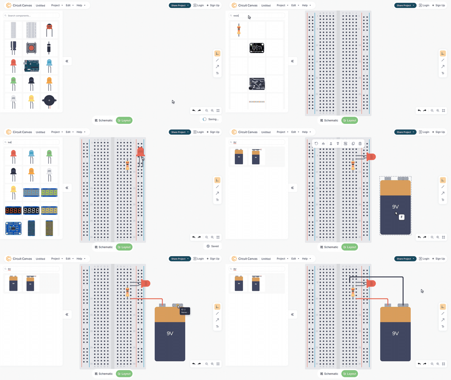
For a full walkthrough on a breadboard, see How to Plan a Breadboard Layout.
Making It Easy to Follow
A good illustration is one that someone else can build from without asking you a single question. A few habits make a big difference.
Use colours that mean something. Red for positive and black for ground is what most people expect, so stick to it. If you have a few signal wires, give each type its own colour and keep it the same throughout.
Keep wires short and flat. A wire that runs straight along the board is easy to follow with your eye. One that loops across half the breadboard is not. If you find yourself drawing a long wire, try moving a component instead. Often, moving a part one or two rows removes a crossing wire altogether.
Point every chip the same way. If pin 1 is always at the top left, nobody has to stop and work out which way a chip is turned. Turning a chip around is one of the most common mistakes on a breadboard, so make it easy to get right.
Show one step at a time. In a tutorial, a series of pictures that each add a few parts is much easier to follow than the finished circuit on its own. Start with just the chip on the board:

Then add the power wires, then the timing parts, and so on. Since every step is the same project with a few more parts, you can make the whole series by saving a copy of the illustration as you go.
Getting It Out of Circuit Canvas
When the illustration is finished, you can export it as an image for a blog post, a worksheet or a video. Or copy it to the clipboard and paste it straight into a document, an email or a forum reply, without saving a file first.

You can also share a link to the project. Anyone with the link can open it, zoom in on the part they're unsure about, and switch to the schematic to see how the circuit works. That's often the best of both worlds: the illustration to build from, and the schematic one click away.