
How to Plan a Breadboard Layout
Before I start building a circuit on a breadboard, I like to know where everything goes. Otherwise I tend to run out of room halfway through, end up with long jumper wires crossing the whole board, or plug a leg one row off and spend twenty minutes finding out why nothing works.
Planning the layout in Circuit Canvas takes a few minutes, and moving a component on the screen is a lot quicker than pulling it out and pushing it back in. You also end up with a picture you can build from, and one you can give to anyone else who wants to build the same circuit.
How a Breadboard Is Connected
To plan a layout, you need to know which holes are connected to each other inside the breadboard. There are two areas to know about.
Power Supply Columns
The columns along the left and right edges are connected vertically, all the way down. If you connect 5 volts to the top hole of one of them, every hole in that column has 5 volts. Use the column marked with a red line for plus and the one marked with a blue line for minus.
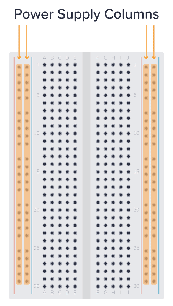
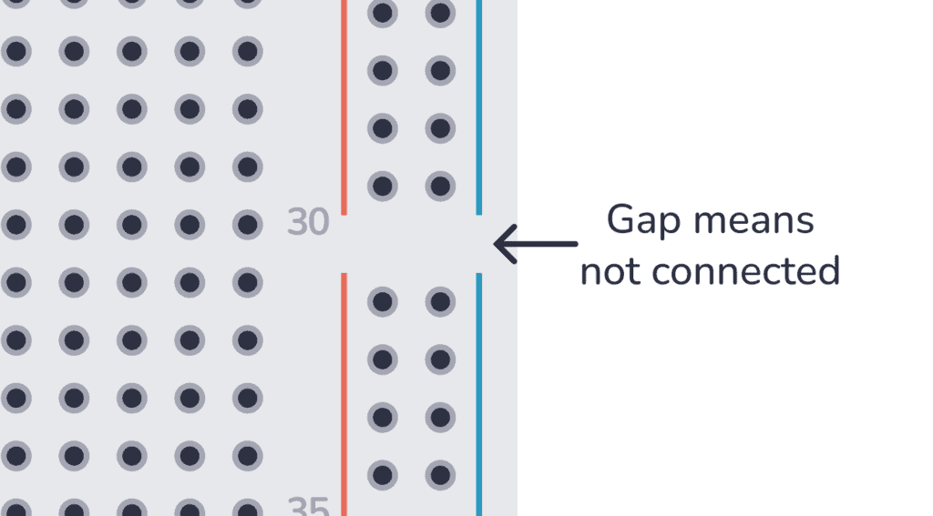
Some larger breadboards split these columns in two, so the upper half isn't connected to the lower half. You can see it where the red and blue lines have a gap.
Component Area
In the middle is where the components go. Here the holes are connected horizontally, in rows, and the left side of the board is separated from the right side.
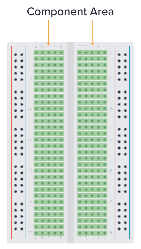
So the legs of a component have to be in different rows, or on different sides of the gap, or they're shorted together. To connect something to a leg, plug it into the same row:
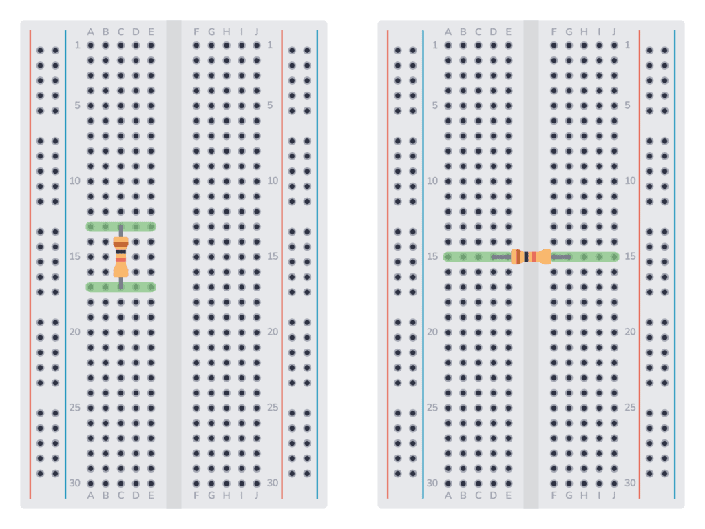
A chip goes across the gap in the middle, so each pin gets its own row:
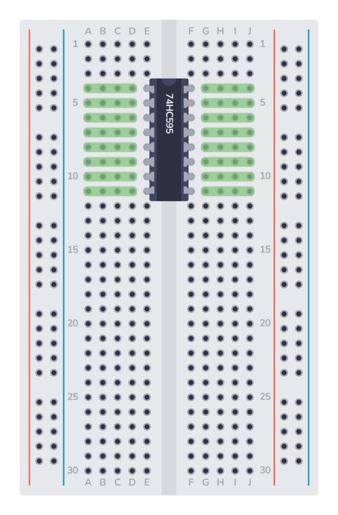
For the full beginner's guide, including which wires fit best, see How To Use A Breadboard on Build Electronic Circuits.
Step 1: Start With the Schematic
Draw the schematic first. On the schematic canvas you only think about what the circuit should do: which components you need and what connects to what. You don't have to think about where anything physically goes. Get the functionality where you want it before you think about placement.
The schematic and layout canvases are linked, so every component you add to the schematic is added to the layout as well, with the same reference and value. When you switch to Layout mode, all your parts are already there, waiting to be placed on a breadboard.
Step 2: Add a Breadboard
In Layout mode, start by adding a breadboard from the component chooser. There are three sizes:
- Breadboard Mini: for small circuits with a handful of components.
- Breadboard Half: the common size most people have on their desk.
- Breadboard Full: for bigger circuits, or when you want plenty of room.
 |
-2025-01-09T06-54-22-981Z-mudsptte2766e6.png) |
-2025-01-09T06-54-23-187Z.png) |
| Mini | Half | Full |
Pick the one that matches the breadboard you actually have, so your plan fits the real thing.
Step 3: Place the Components
Drag each component onto the breadboard; the legs snap into the holes. A few things that make a layout easier to build and to follow:
- Start with the biggest part, usually a chip or a module, and place everything else around it.
- Put chips across the middle gap, so each pin gets its own row.
- Keep connected parts close together. If two legs need to connect, try to put them in the same row so you don't need a wire at all.
- Use the power supply columns for plus and minus, so every component can reach them with a short wire.
You don't have to keep the schematic in your head while you do this. Turn on the rats nest (Project > Verify Connections > Show rats nest), and Circuit Canvas draws a thin line between every pair of pins that should be connected according to your schematic, but aren't connected yet. As you place parts in the same row or add wires, the lines disappear. When there are none left, everything is connected.

This is where planning pays off. Try a placement, look at it, move things around. It costs nothing, and the rats nest shows you straight away which placement needs the fewest wires.
Step 4: Add the Jumper Wires
Click on a pin to start a wire, and click where it should end. Give the wire colours a meaning, for example red for plus and black for minus, so the finished plan is easy to read. Short, tidy wires are also much easier to check than long ones crossing the board.
You can also turn on Show incorrect connections in the same Verify Connections window. It marks anything you've connected that isn't connected in the schematic, like a leg one row off.

Bonus: Your Plan Is Also Build Instructions
A schematic says what connects to what. A breadboard layout shows exactly which hole each leg goes into, and for a beginner that's often the difference between a circuit that works and one that doesn't.
If you're writing a tutorial, answering a question on a forum or teaching a class, add a few arrows (shortcut A) and some text (shortcut T) to point out the tricky parts, like which way the LED goes. Then use Export as Image, or make the project public and share the link.
When It Works, Make It Permanent
Once your circuit works on the breadboard, you can plan the soldered version in the same project. See Planning Your Stripboard or Perfboard Layout.