How To Design Custom Components for Circuit Canvas
Circuit Canvas is a tool to easily design good-looking schematics and wiring diagrams for breadboard, perfboard, and other prototyping boards. You can design your own custom components by simply creating a vector drawing of your component in SVG. But to make them snap into the grid and automatically recognized connection points, there are a few details that you need to pay attention to.
You can download an example custom part for Circuit Canvas schematics view here: custom-schematic-symbol.svg
Note: We also support importing components made for Fritzing in the Layout canvas. So if you already made a component for fritzing, just drag and drop it into the Layout canvas to import it. Or use our Fritzing Converter Tool to convert it to a Circuit Canvas compatible SVG file that you can make changes to.
Step 1: Setup grids, scale, and units
You need to draw your component as a vector file. We recommend using Inkscape which can be downloaded for free from this link.
To make the component work with the grid in Circuit Canvas, set your document grid to 5px for schematic components, or 2.5px for layout components. And set the scaling to 1. All units must be in pixels.
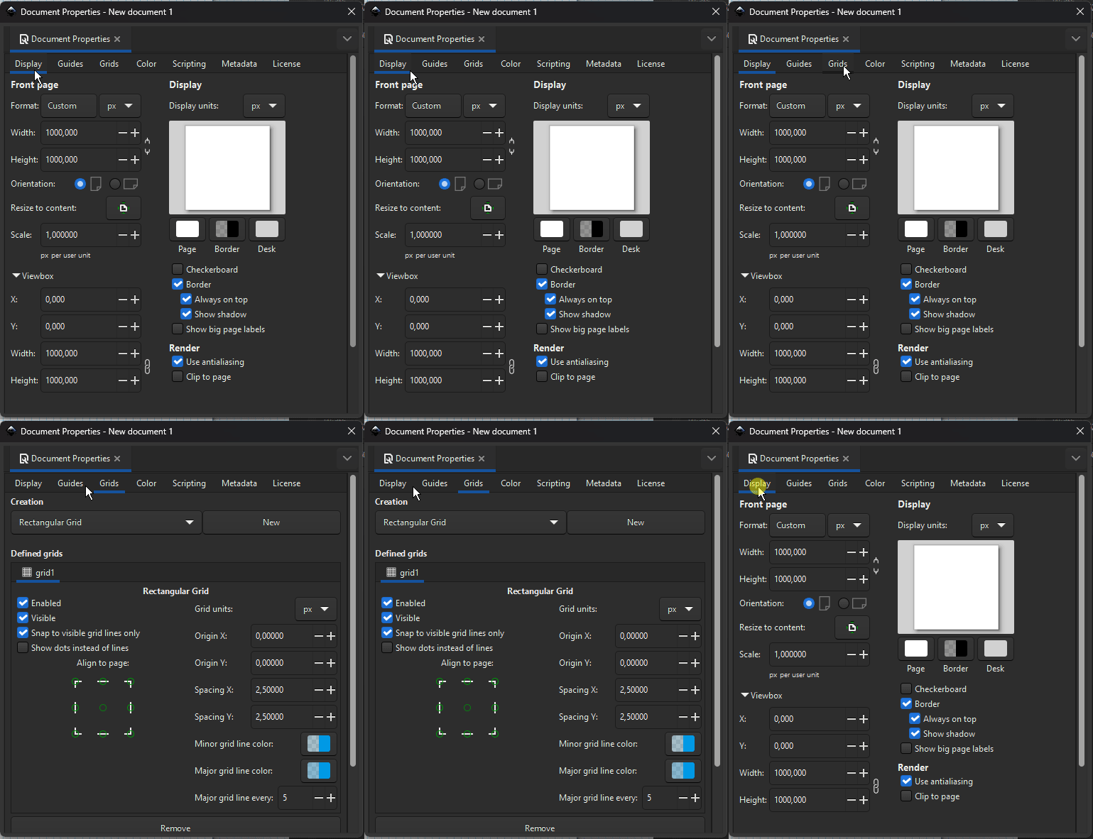
Step 2: Draw your component
Once you've setup the grid, scaling, and units, you can start drawing your component.
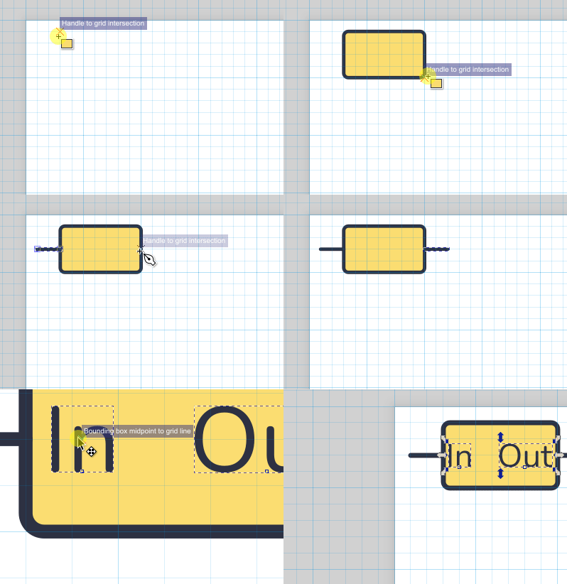
Remember that schematic components use a different grid (5px) than layout components (2.5px). And make sure all units are in pixels to avoid issues.
Step 3: Prepare your document and save it
Once you're happy with your drawing, you need to add connection points. A connection point is a circle with the class "connection_point". For now, just add a circle with a fill color where you want the connection point. All connection points should be placed on a grid-point. And they should be on top of everything else.
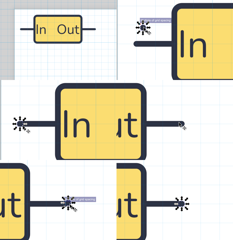
Resize your document to the size of the component. The size should be a multiple of the grid size. For example for a schematic component that uses a 5px grid, the width could for exampel be 45px or 50px. But it can't be 43px.
Whitespace on the sides or top/bottom is fine. Try to place your component in the center. Make sure your connection points are on the grid.
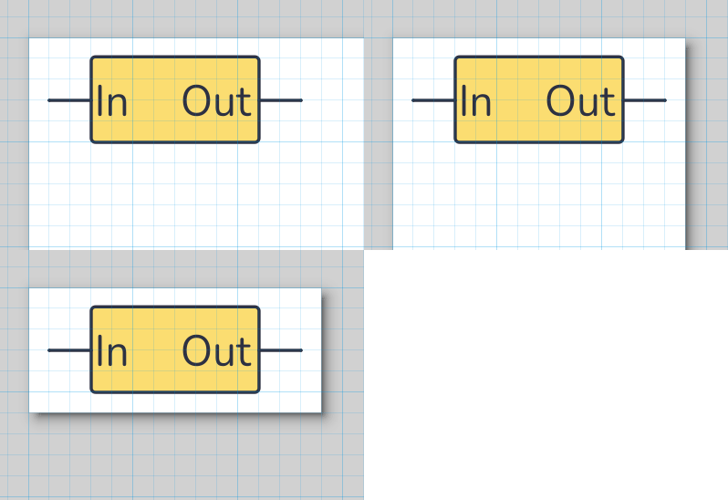
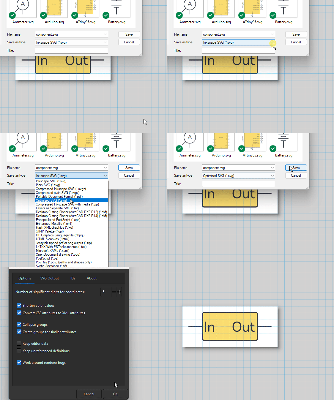
Save your component as Optimized SVG.
You'll find that by choosing "Save As" in Inkscape. In illustrator, I'm not sure, but try to find something that will save in plain svg with all styles as attributes, not css.
Step 4: Define your connection points
Now that you've saved your svg file, the last step is to add the "connection_point" class to the circles that represent your connection points. Open your saved svg file in a text editor and locate the circles. Add class="connection_point" to the circle. Example:
<circle class="connection_point" x=5 y=10 r=1.5 fill="000000">
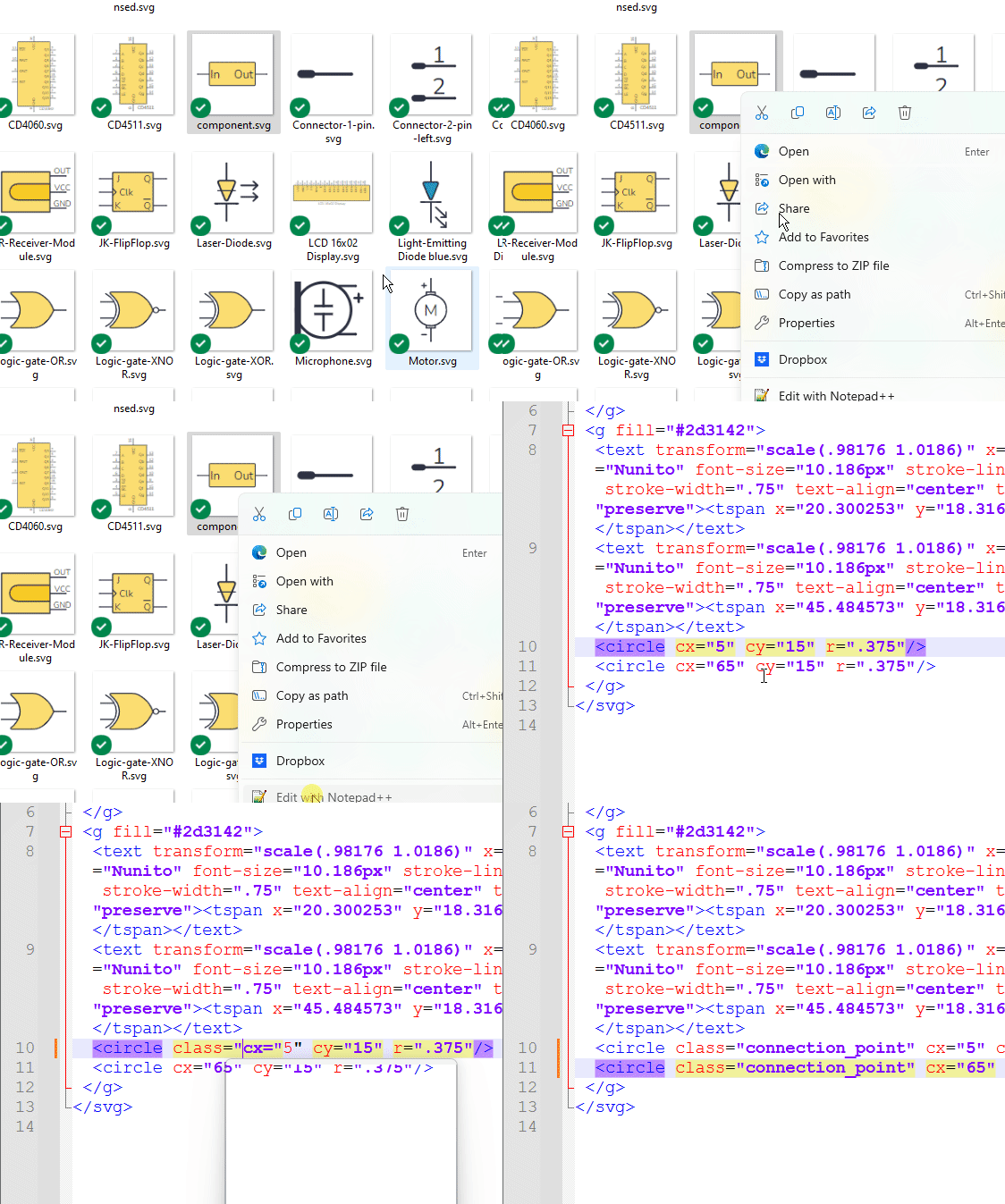
Save your file, and you're ready to import the component!
Step 5: Importing the component
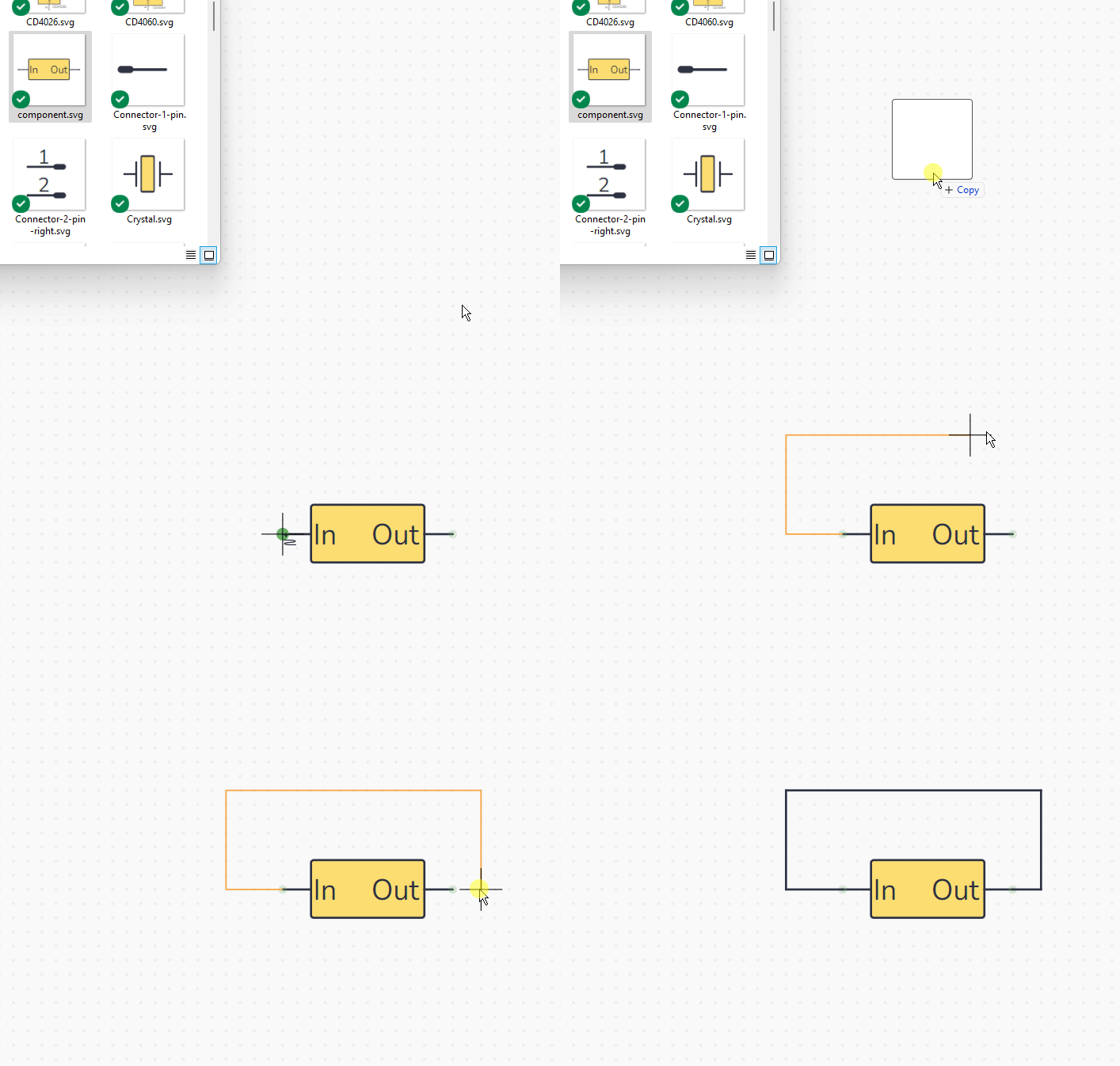
To import your custom component into Circuit Canvas, just drag and drop it into the correct canvas!
There's also an "Import Component" item under Project in the top menu that let's you import components. And by the way, our import tool also supports conversion from Fritzing ;)
Questions, feedback, requests?
We want to make this the best tool there is to easily draw beautiful circuits for teaching, sharing, documentation, and whatever else you need it for!
If you have any questions, feedback, or feature requests, you can get in touch by sending an email to info@circuitcanvas.com.
